
Home / Fanuc UK Stock / Fanuc Alarm Codes / Fanuc Beta Alarm Codes
FANUC Spindle Alarm Codes
6093
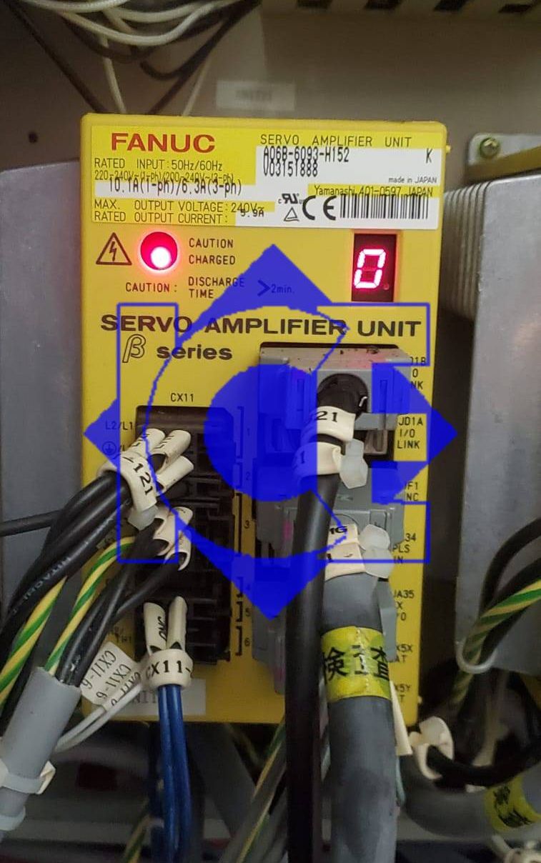
- O
Drive ready no faults active
000 U
A parameter that requires power down has been specified
011 F
The specified feedrate is zero
013 F
The specified feedrate ( max feedrate) is zero
070 t
More than 32 blocks have been registered for a buffering operation
085 h
Input from the reader/punch interface or the like caused an overrun, parity or framing error
086 h
Input from the reader/punch interface or the like includes an input/output unit operation ready signal (DR) that is set to off.
087 h
After input form the reader/punch interface or the like stops, character input does not stop even though ten characters have been input.
090 9
Reference position setting cannot be executed normally.
093 u
A first to third reference position return cannot be executed because the reference position has not yet been established.
224 u
The reference position has not yet been established. This occurs only when the ZRTN bit of parameter No.0001 is set to 0.
250 7
Input data 1 is invalid
251 7
Input data 2 in invalid
255 n
Operation cannot be activated because an invalid mode is specified or because block execution is in progress.
290 _
The interface switch signal (DRC) was switched during block execution.
291
The speed of an axial movement specified by an external pulse has exceeded the upper limit. This occurs only when the EPEXA bit of
parameter No.0001 is set to 1.
292
A checksum error for the battery powered memory was detected.
Pulse coder Alarms
300 5
A communication error (DTER) for the serial pulse coder was detected.
301 5
A communication error (CRCER) for the serial pulse coder was detected.
302 5
A communication error (STBER) for the serial pulse coder was detected.
303 6
An LED disconnection (LDAL) was detected in the serial pulse coder.
304 6
A mispulse alarm (PMAL) for the serial pulse coder was detected.
305 6
A miscount alarm (CMAL) for the serial pulse coder was detected.
306 3
The motor was overheated (OHAL)
308 6
A soft phase alarm (SPHAL) was detected.
319 11
When the absolute pulse coder is used, the motor has not yet rotated through more than one turn after the first power up.
350 2
The battery voltage of the absolute pulse coder is low.
351 1
The battery voltage of the absolute pulse coder is low ( warning).
400 4
The servo motor has overheated (estimated value)
401
Servo amplifier ready signal (DRDY) went off.
403 o
The cooling fans have overheated.
404 J
The regeneration discharge has over heated
405 n
Reference position return could not be executed correctly.
410
The servo position error in the stop state is larger than the value specified in parameter no 110.
411
The servo position error during movement is larger than the value specified in parameter no 182.
412 c
An overcurrent alarm is issued
413 y
A DC link overvoltage alarm is issued.
414 P
A DC link low voltage alarm is issued.
417 A
A parameter has been specified incorrectly.
418 E
A DO alarm is issued
423 t
The specified speed excess 32767000 detection units per second.
425 C
The cooling fan has stopped.
Overtravel Alarms
500 H
The positive stroke limit has been exceeded
501 H
The megative stroke limit has been exceeded
510 H
The positive soft stroke limit has been exceeded
511 H
The negative soft stroke limit has been exceeded
System Alarms
– E
An error was detected in the RAM write/read test at power up.
– 8
An error was detected in the data collection check for the battery powered memory.
– 9
A data transfer alarm for the battery powered memory has been issued.
– d
A watchdog was issued.
– b
A checksum alarm for the control software ROM is issued.
– 9
A checksum alarm for the ROM that is built into the CPU is issued.
– .
An error was detected in the control circuit.
I/O Link Alarm
– L
A FANUC I/O link error occurred. A unit connected to the line was turned off
No LED Display
– No indicators Lit The control circuit is not operating normally